At present, the extending of a face to face instruction is limited and every schools are looking for a solution that can provide such understanding and skills.
Well, the long wait is over because new-age learning tools are already available in the form of virtual simulators.
Our partner industry, Anucool Engineers from India that manufactures Refrigeration and Airconditioning Systems both for commercial and training applications also developed Virtual Equipment & Simulation Modules in Refrigeration & Air Conditioning Laboratory, designed to fulfill several objectives. With Anucool Engineers’ vast experience of manufacturing laboratory equipment, it provides modules with right learning objectives and methodology.
Students can perform several tests for the interdependence of parameters which is beyond the range when performing it in an actual physical setup.
Data-driven models are used to ensure that the applications resemble real-life machines as closely as possible.
We are looking forward to positive reply for a demo.
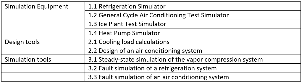
LIST OF VIRTUAL SIMULATORS FOR REFRIGERATION AND AIRCONDITIONING TEST RIGS
REFRIGERATION TEST SIMULATOR
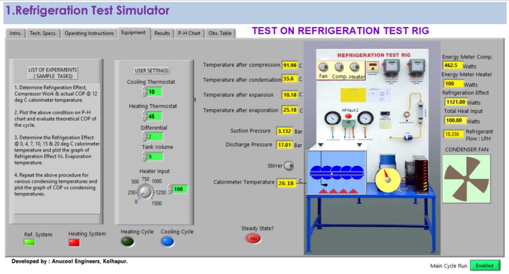
Above is the image of the front panel of the virtual Refrigeration Test Rig. You can conduct trials, same as that on the actual one.
List of experiments:
- Determine the actual and the theoretical COP of the system.
- Plot the process on the P-H chart.
- Determine the refrigeration effect at various calorimeter temperatures and plot the graph of Refrigeration Effect Vs. Evaporating temperatures.
- Perform the above tests using a capillary tube and thermal expansion valve.
- Conduct the above tests choosing different refrigerants.
Salient Features:
- Choice of multiple refrigerants such as R134a, R404A, R22, R600, R407C
- Choice of expansion device: Capillary tube & TEV.
- Accurate simulation of parameters.
- A real-time demo of processes
- Data logging and report generation tool.
Switches, Controls & Indicators
- Switches: Fan, compressor, heater
- Controllable Parameters: Compressor cut out and cut in temperature, heater cut out and cut in temperature, calorimeter tank volume, heater load input, stirrer on-off, selection of refrigerant, range of expansion device
- Observable parameters: Suction pressure, discharge pressure, temperature after compression, after condensation, after expansion and after evaporation, compressor input, refrigeration effect.
AIR CONDITIONING TEST SIMULATOR:
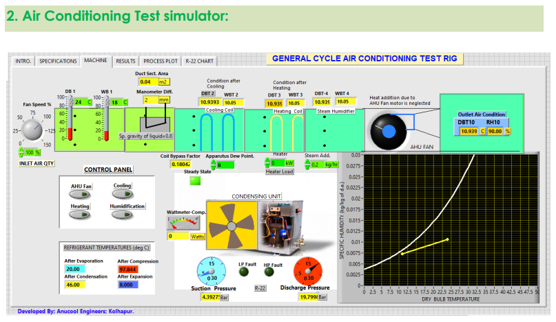
Several tests can be conducted using the above setup.
List of experiments:
- Determine the air conditioner capacity in TR by the enthalpy difference method.
- Determine the actual and theoretical COP of the system.
- Demonstrate various psychrometric processes and plot them on the psychrometric chart.
Salient Features:
- Choice of multiple refrigerants such as R134a, R410A, R22, R407C
- Accurate simulation of parameters
- A real-time demo of processes.
- Data logging and report generation facility.
Switches, Controls & Indicators
- Switches: AHU, Cooling, Heating, Humidification
- Controllable Parameters: Ambient temperature, inlet air quantity, apparatus dew point, coil bypass factor.
- Observable parameters: Suction pressure, discharge pressure, temperature after compression, after condensation, after expansion and after evaporation, compressor input, refrigeration effect, condition of air after each stage
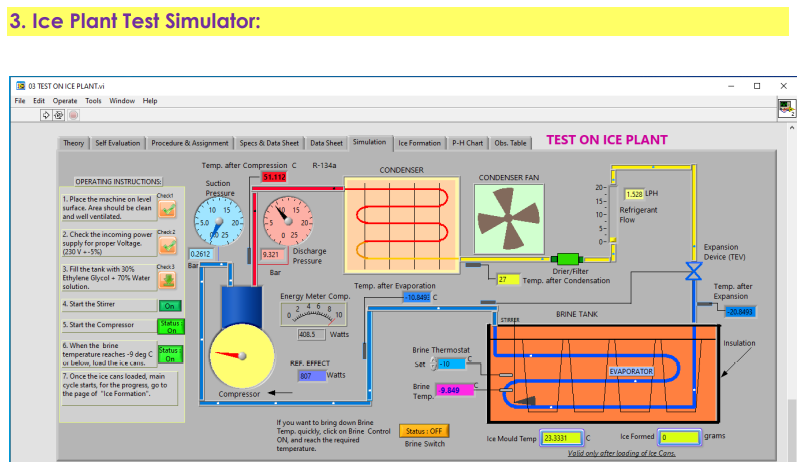
ICE PLANT TEST SIMULATOR
.
The ice plant test rig is a versatile equipment. You can conduct an ice formation test, see how ice formation takes place, see what the instantaneous rate of heat transfer is, and know the overall heat transfer coefficient.
List of experiments:
- Determine the capacity of the ice plant
- Conduct an ice formation test and determine the actual & the theoretical COP of the system
- Plot the process on P-H chart
Salient Features:
- Accurate simulation of parameters.
- A real-time demo of processes
- Data logging and report generation facility.
- The User can also accelerate the process, implying he/she can fast forward the clock.
Switches, Controls & Indicators
- Switches: Stirrer motor, filling of brine, loading of ice cans, brine temperature control switch, compressor
- Controllable Parameters: Refrigeration effect (Process acceleration)
- Observable parameters: Suction pressure, discharge pressure, temperature after compression, after condensation, after expansion, and after evaporation, compressor input, overall heat transfer coefficient, the progress of ice formation, energy consumed.
HEAT PUMP TEST SIMULATOR
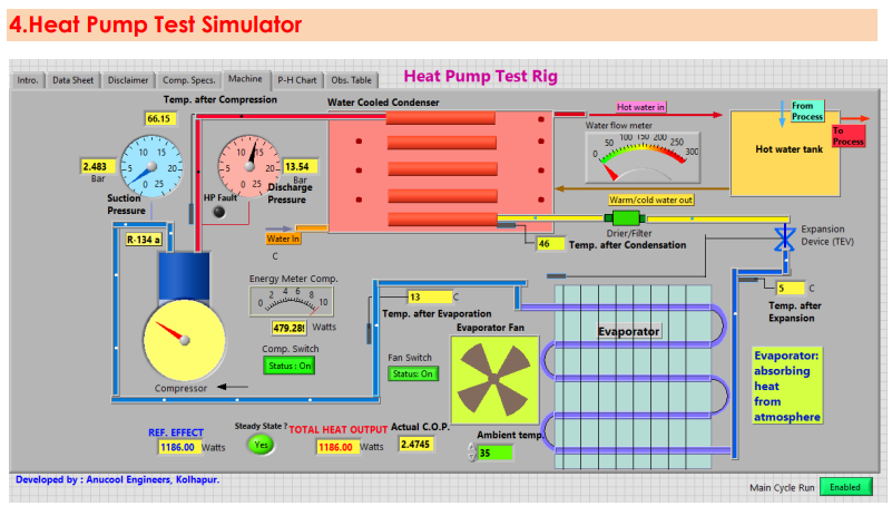
The air to water heat pump enables to conduct the trials at various conditions and determine the heating performance of the system.
List of Experiments:
- Determine the COP of the heat pump
- Assess the variation of ambient temperature and the heating output.
- Determine the water side and the air-side heat transfer coefficients of the system.
Salient Features:
- Ambient temperature variation is possible.
- Choice of multiple refrigerants: R134a and R407C
- A real-time performance.
- Report generation facility
Switches, Controls & Indicators:
- Switches: Compressor, pump, fan
- Controls: Water flow, fan speed, ambient temperature, inlet water temperature.
- Indicators: Suction pressure, discharge pressure, evaporating temperature, condensing temperature, input energy to the compressor, pump and fan, temperatures at salient points in the cycle.
DESIGN TOOL
These are professional-level tools and can be used for projects, research, and development work.
1 Cooling Load Calculations
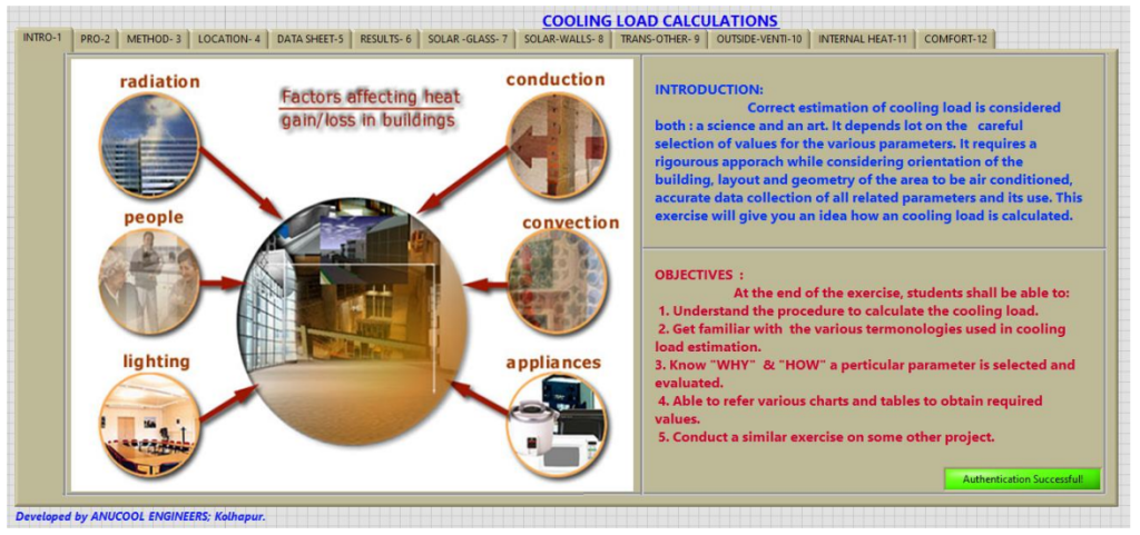
Description of the application:
This application gives a scientific approach to estimating the cooling load with utmost accuracy. It not only computes the values but explains the basis of calculations and the reasoning behind it.
Correct estimation of cooling load is considered both: a science and an art. It depends a lot on the careful selection of values for the various parameters. It requires a rigorous approach while considering the orientation of the building, layout, and geometry of the area to be airconditioned, accurate data collection of all related parameters, and its use. This exercise will give you an idea of how a cooling load is calculated.
Salient Features:
- Heat transfer coefficients of standard construction material are pre-coded.
- Ventilation standards as per ISHRAE norms mentioned and considered for calculations.
- Simple and easy to fill datasheet.
- User friendly interface.
- Report generation facility.
2 Design of an Air Conditioning System
It is a comprehensive package which guides you right from the beginning through a step by step procedure to design an air conditioning system.
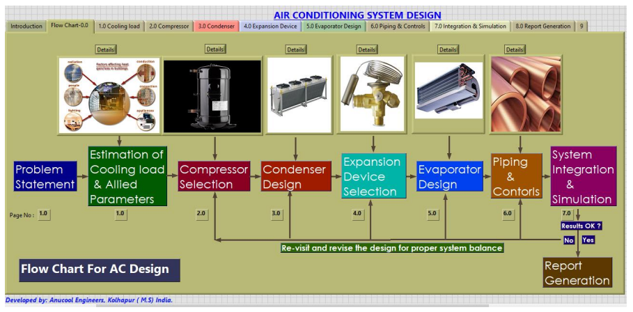
Product Description:
An air conditioning system consists of several subsystems. For each subsystem, the design procedure is elaborated with standard practices and codes, with a theoretical basis.
Finally, all subsystems are integrated (just like the assembly of physical systems), and the performance is simulated.
The system does not run until the parameters pertaining to all the subsystems are in harmony and balance.
The uniqueness of our tool lies in this integration!
Salient Features: The subsystems are:
- The set up begins with a problem statement and ends with a solution and report generation.
- Cooling Load Estimation: The application no 1 Cooling Load Calculations is a part of this setup. Once the cooling load and other parameters required are determined, you can go to the next stage.
- Compressor Selection: With given conditions, how to select a compressor is explained. For reference, the manufacturer’s catalogues are provided. Capacity: 1.0 TR to 25.0 TR
- Condenser Design: Design procedure for the air-cooled and water-cooled condenser. Determination of primary surface area, secondary surface area, air, or water quantity required. Selection of fan and/or a pump
Expansion Device: Selection of expansion device based on capacity, refrigerant, condensing temperature, evaporating temperature, orifice number.
- Evaporator Design: Determination of overall heat transfer coefficient under the given conditions. Surface area calculations. Determination of cooling coil size, number of rows.
- Piping and controls design: Piping sizes for suction line, discharge line, liquid line. Thermostat and pressure cut cutout setting
- System integration & simulation: Integration of subsystems to build total system. If the system is balanced, the report will be generated; else, design revision is be required.
SIMULATION TOOLS:
These tools help to ascertain the system parameters under varying conditions. One of the unique features of such setups is the great liberty in control parameters.
THE COMPUTATIONS ARE NOT STRICTLY ANALYTICAL, THEY ARE RATHER DATA DRIVEN WITH ALL THE SUBSYSTEMS BEHAVING AS A REAL MACHINE WOULD.
1 Steady State Simulation of Vapor Compression Cycle.
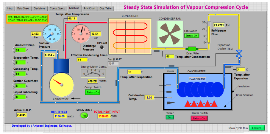
Product Description:
As the name suggests, this set up ‘SIMULATES’ the actual conditions of a Vapor Compression Cycle. It consists of a hermetically sealed compressor, forced convection air cooled condenser, a fan motor, filter / drier, a flow meter, an expansion device, and a shell & coil evaporator placed in an insulated vessel (calorimeter). This is a powerful tool to understand the process and the relative interdependence of parameters and performance of the system
Salient Features:
- You can vary condensing temperature and evaporating temperature, and observe effect on refrigeration effect, compressor work & C.O.P. of the system.
- Variation in degree of superheat and that of sub-cooling is also possible on this application.
- The user can record all the readings and plot the graphs of various parameters to establish relationship and the interdependence.
2 Fault Simulation of Refrigeration System:
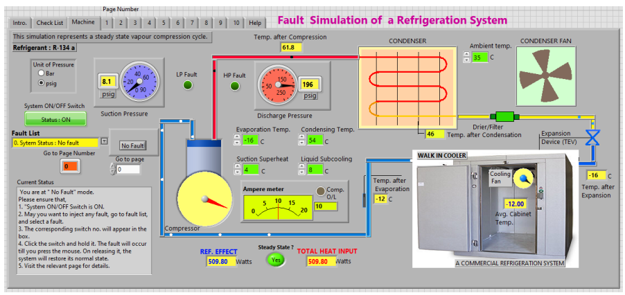
Product Description:
There is a normally working vapor compression refrigeration system operating under certain conditions. With the help of controls provided, a fault can be injected.
The system behaves, as if it is in faulty condition.
This is a data driven simulation of faults, uniquely combined with working system.
The same description is applicable for Air Conditioning Fault Simulator.
3 Fault Simulation of an Air Conditioning System
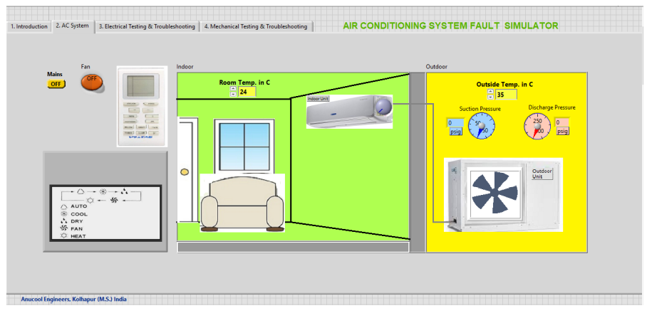
In both the cases, 2 Fault Simulation of Refrigeration System and 3 Fault Simulation of an Air Conditioning System several electrical and mechanical faults can be injected, and system behavior can be studied.
Some of faults are:
- Capacitor fault
- relay fault
- MCB fault
- OLP fault
- Compressor ground fault
- Compressor open winding
- Compressor draws heavy current
- Compressor pumping failure
- System undercharged
- System overcharged
- System tripping on HP and LP cut out
- High discharge pressure
- Evaporator chocked
- Air filter blocked
- Condenser blocked
- Low suction pressure
- Drier chocked, and such faults
These faults can be injected, rectified and system can be restored to normal working conditions.
For inquiries, please feel free to contact our technical specialist manager in Mechanical: