The first operational modern jet engines were developed by Sir Frank Whittle of England and Dr. Hans von Ohain of Germany in the 1930’s. It was initially designed to be used for military aircraft in order to achieve higher speeds than the propeller driven planes. Today, jet engines are used by both the military and civilian aviation because of its increased capability and efficiency as compared to the early designs. The first Gas Turbine was first used in a Royal Navy ship in 1947 as its main propulsion because of the high power-to-weight ratio, high acceleration and ability to get underway quickly. In the following years it was also installed in some commercial ships but mainly to drive generators. One such vessel is the cruise ship Queen Mary 2 which uses six(6) generators; four are diesel driven while two are driven by gas turbines. The six generators are needed because of the high hotel load and to power the four mammoth electric Azipods for the ships propulsion in order to attain a maximum speed of around 30 knots.

Requirements for the Bachelor of Science in Marine Engineering(BSMarE)
Based on the Revised Curriculum for Bachelor of Science in Marine Engineering (BSMarE) in compliance with CHED Memorandum Order # 67 series of 2017, an actual Gas Turbine may be utilized for the following subject in BSMarE course namely: Propulsion Ancillary System & Gas Turbine (PASGT). One such equipment that complies with the course description is the MT 560 TWO-SHAFT GAS TURBINE from ESSOM.
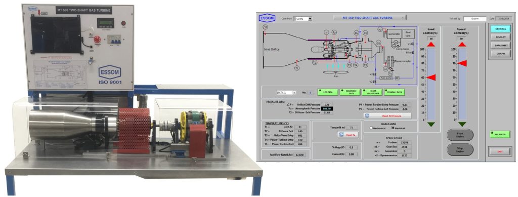
MT 560 TWO-SHAFT GAS TURBINE
GENERAL DESCRIPTION
The turbine is a small two-shaft gas turbine engine with a radial flow compressor and axial flow turbines as in the modern gas turbine power plant.
The first shaft is a hot gas generator. Inlet air through an orifice flow measuring device is compressed by a single stage radial flow compressor. The turbine is motor started and runs on Jet A fuel. Fuel is injected by a fuel pump and ignited in the combustion chamber providing hot gas for a single stage axial flow turbine which inturn drives the compressor. The hot gas is discharged axially to a larger power turbine on the second shaft and exhausts to atmosphere. A fan is provided for cooling the gear box.
Speed of the power turbine is reduced by the gear box. A water brake absorber is connected to the gear box for power measurement. The brake requires outside water supply. Load is manually controlled.
An Electronic Control Unit (ECU) controls the basic turbine operation. Additional instruments are provided for monitoring and controlling turbine performance.
A touch screen computer with an interface unit and software are provided for speed and load control, data display and analysis, and to assist the ECU.
Safety features include clear acrylic cover, gas generator over speed shutdown, power turbine over speed protection and power turbine entry over temperature shut down. The unit is floor standing with removeable supports. Instruction manual is also included.
TYPICAL EXPERIMENTS
- Understanding the thermodynamic process.
- Torque vs speed.
- Power input and output and engine efficiency.
TECHNICAL DATA
Gas generator construction:
| Diffuser | High strength aluminium |
| Combustion chamber | Stainless steel |
| Bearings | Ceramic ball bearing |
| Turbine wheel | Vacuum cast inconel |
| Compressor | High grade aluminium alloy |
| Gas generator | |
| Starting and running fuel | Jet A or kerosene with jet oil |
| Power turbine | |
| Turbine wheel Interstage guide vane | Vacuum cast inconel |
| Interstage guide vane | |
| Gear box | |
| Type | Planetary |
| Lubrication | Jet A |
TECHNICAL DATA
| Dynamometer(with water cooling unit with pump instead of outside water supply) | |
| Type | Water brake absorber |
| Maximum power | Approx. 5 kW |
| Gear box and dynamometer connection | Direct coupling |
| Output power | |
| Mechanical | Approx. 700 W |
| Sensors | |
| Temperatures | Inlet air, diffuser exit, gas generator turbine entry, power turbine entry and exit |
| Pressures | Diffuser exit, power turbine entry and exit |
| Speeds | Gas generator and gear box output shaft |
| Dynamometer torque | |
| Fuel flow rate | |
| Air flow rate | Differential pressure at inlet orifice |
| Accessories | Engine cooling fan Gear box cooling fan Engine exhaust duct 2 Ear muffs Jet oil Barometer |
| Power supply | 220V, 1 Ph, 50Hz. Other power supply is available on request |
Why use ESSOM Products?
Quality assurance
ESSOM has been certified ISO 9001 Quality Management System since 1999. The scope of certification includes Design and Manufacturing of engineering equipment as well as Sales and Service of both engineering education and paint spray equipment. All the engineering education products have been designed by their experienced and well qualified engineers. Prototypes must pass design test standards before market introduction. Parts and materials are sourced from approved supplier/material lists and must pass receipt inspection. In-process inspection is carried out at key manufacturing stages with final inspection after completion. All new products must pass strike design test before market introduction.
Market
With ESSOMs global marketing network of agents and sales partners they have now supplied their equipments to over 50 countries.
References:
- ESSOM
- GE Marine: Efficient, Reliable Power for Military
- Lancashire CGI studio reappointed by Rolls Royce for marine turbine brief Prolific North
- Marine Gas Turbine Engines I Marine-Knowledge I Your Trusted Source For Marine Related Info
Contact us: